Encrypt your home Folder in Linux.

This guide will lead thought the process of creating a encrypted container and automatically mount it as home partition.

This was tested with Ubuntu 20.04.

Preparation

  • Create a partition on a block device or add a new block device if you want to use it full.
  • Consider save erasing the device before, if any sensible data was stored there before.

Encrypted Container

This guide will utilize cryptsetup to create a LUKS header on a given device.

⚠️ All data of the used partition or device will be lost.

Creation of the LUKS Header

Install ‘cryptsetup’ via APT.

sudo apt install cryptsetup

Use the command cryptsetup to setup the header. Replace the device with your block device or partition.

cryptsetup <options> luksFormat /dev/sdX

You can supply non standard options. See https://wiki.archlinux.org/title/Dm-crypt/Device_encryption#Encryption_options_for_LUKS_mode for more information.

Create a Filesystem.

After creation of the header, the container can be encrypted.

cryptsetup open /dev/sdX <name>

The name can be chosen arbitrary for now. The service will create a block device on /dev/mapper/<name>. After that the file system can be created.

mkfs.ext3 /dev/mapper/<name>

Note: The filesystem can be chosen freely.

Mount as Home Partition.

⚠️ At least one password of the above created container needs to match the password of the user that should login. If no password matches, the container cannot be unlocked!

Copy Content of Current Come Folder.

In order to mount the encrypted container as a home partition of a user, first the current data has to be copied:

mkdir /media/new_home
mount /dev/mapper/<name> /media/new_home
rsync -avx /home/<user>/ /media/new_home
umount /media/new_home
rm -rf /media/new_home

Note: In order to lock a container use cryptsetup close <name>.

Note: After the successful installation of the mounting process, delete /home/<user> via an admin account.

Automatically Mount the Container.

First the package libpam-mount-bin needs to be installed, enabling PAM to mount at login or other authentication actions.

sudo apt-get install libpam-mount-bin

Installing libpam-mount-bin creates a default configuration at /etc/security/pam_mount.conf.xml. Adding the following snipped after <!– Volume definitions –> will instruct PAM to unlock the given ‘path‘ with the user password from login and mount it to ‘mountpoint‘.

<volume     user="<USER>"
            fstype="crypt"
            path="/dev/disk/by-uuid/<UUID>"
            mountpoint="/home/<USER>"
            options="fsck,relatime"
/>

To get the uuid, use ls and chose the device that was encrypted with the cryptsetup command from above.

ls /dev/disk/by-uuid/ -la

Notes

Swap

The Kernel might write data to the swap partition during system runtime. This data might not get erased and could be recoverable after shutdown or crash of the system.

During hibernation the password for the opened container will be written in plain text to disk. Therefore consider disabling hibernation or encrypt swap as well.

Note: Disabling swap completely on systems with more than 8 GB RAM can be considered safe.

TEMP Folder (/var/tmp)

The TEMP folder contains data that programs have usually currently in use. If a program opens data from the encrypted partition, the program can potentially have parts of the date stored to /var/tmp during execution. Intentionally or unintentionally this data can persist in /var/tmp after termination or a crash.

Usually the /var/tmp folder can be moved safely to RAM or can even be encrypted as well.

Note: Moving /var/tmp to RAM is commonly used by distributions and on single board computer and can be considered safe.

Note: Moving /var/tmp to RAM will cause a full data loss of temporary data during power failure or reboot.

Locate

Locate is a commonly used tool to quickly locate files in the file system. In order for this quick lookup, a database of the files is created and maintained.

Crawling and indexing the encrypted container during system run-time can pose a security risk. Consider therefor disabling crawling of the mounted container with correct configuration of /etc/updatedb.conf.

OpenSSL Cheat Sheet

Tested with OpenSSL 3.0.8 7 Feb 2023 (Library: OpenSSL 3.0.8 7 Feb 2023) on (K)Ubuntu 23.04.

Certificate Revocation Status

Verify Status with CRL

OpenSSL does offer the option to connect to a server and verify its certificate against the published CRL via the s_client sub-command [1].

The following example does perform a verification, including a CRL check of google.com.

openssl s_client -crl_check -crl_download -connect google.com:443 < /dev/null

Note: -crl_check_full might most likely fail, either because the ROOT certificate does not provide a CRL or it does provide an empty CRL [2].

Verify Status with OCSP

OCSP requests can be send by the ocsp sub-command [3].

First, the certificates need to be made locally available:

openssl s_client \
    -connect google.com:443 < /dev/null \
    -showcerts \
| awk '/BEGIN CERTIFICATE/ { i++; } /BEGIN/, /END CERT/ { if(i==1) print > "server.pem"; else print > "intermediate" i-1 ".pem";  }'

This one-liner uses awk to split the downloaded chain (note the -showcerts option) into a server.pem and all following into intermediate[i].pem files.

These files can then pe placed into another one-liner and use the ocsp sub-command to send a verification request [4]:

openssl ocsp \
    -issuer <(find . -iname "inter*.pem" | sort | xargs cat) \
    -cert server.pem \
    -text \
    -url $(openssl x509 -in server.pem -ocsp_uri -noout)

The root certificate will be used from the CA store of the local machine or can be supplied via the -CAfile option.

Certificate and CSR Generation

RSA

In order to create a self-signed certificate, the OpenSSL CSR sub-command req can be used [5].

This command creates an self-signed certificate with the issuer and subject /C=AT/CN=foo and a validity period of 2 years.

openssl req \
    -x509 \
    -nodes \
    -days $((365*2)) \
    -newkey rsa:4192 \
    -keyout selfsigned.key \
    -out selfsigned.pem \
    -outform PEM \
    -subj "/C=AT/CN=foo"

The command creates a private RSA key with 4192 bits and embeds the public key into the certificate. To supply an already generated key, the -key option can be used. To create a new key, refer to Section Generation of a Password Protected Private RSA Key,

To verify the correctness, the x509 sub-command can be used [6]:

openssl x509 -in selfsigned.pem -text -noout | grep -zoP "(Issuer:|Subject:|Validity\n.*\n).*\n"

The output should look like:

Issuer: C = AT, CN = foo
Validity
            Not Before: Oct 26 12:04:46 2023 GMT
            Not After : Oct 25 12:04:46 2025 GMT
Subject: C = AT, CN = foo

Note that Issuer and Subject are identical, this is the definition of self-signed certificate.

ECDSA

A ECDSA private key is needed first and can be forged with the ecparam command [7]:

openssl ecparam -genkey -name prime256v1 -out ec_key.pem -outform PEM

The option -name prime256v1 instructs OpenSSL to use the prime256v1 (secp256r1) parameters.

Verification of the key content can be archived with the ec command [8]:

openssl ec -in ec_key.pem -text -noout

Generation of a CSR works analogous to above explained RSA, with the req command.

openssl req \
    -x509 \
    -nodes \
    -days $((365*2)) \
    -key ec_key.pem \
    -out selfsigned.pem \
    -outform PEM \
    -subj "/C=AT/CN=foo"

Verification is analogous to the RSA key:

openssl x509 -in selfsigned.pem -text -noout | grep -zoP "(Issuer:|Subject:|Validity\n.*\n).*\n"

The output should look like:

Issuer: C = AT, CN = foo
Validity
            Not Before: Oct 26 21:07:45 2023 GMT
            Not After : Oct 25 21:07:45 2025 GMT
Subject: C = AT, CN = foo

Format Conversion of x509 Certificates

The x509 command provides the option to read certificates in format A and convert it to format B:

openssl x509 \
    -in  selfsigned.pem -inform  PEM \
    -out selfsigned.der -outform DER

The diff command can be used to verify the content is identical:

diff \
    <(openssl x509 -in selfsigned.der -inform DER -noout -text) \
    <(openssl x509 -in selfsigned.pem -inform PEM -noout -text) \
    -s

Generation of a Pass Phrase Protected Private RSA Key

Via the genrsa command a RSA private key can be generated [9].

openssl genrsa -out encrypted_key.pem -aes256 3072

The option -aes256 instructs OpenSSL to use symmetric encryption with AES256. The command will ask for a pass phrase within the shell.

Pass Phrase Removal

To remove the pass phrase, simply pass the key though the rsa sub-command [10]. The command will ask for the phrase and pipe the unencrypted key into the file specified with the -out option.

openssl rsa -in encrypted_key.pem -out key.pem

To set a new pass phrase, use:

openssl rsa -in encrypted_key.pem -out other_password_key.pem -aes256

Older Microsoft Hardware Is Not Supported By The New “Mouse and Keyboard Center”

If you have the same problem like me, that the mouse wheel of you beloved Microsoft Wireless Laser Mouse 8000 is not working in some applications and games, you need the Microsoft drivers for it.

Unfortunately, the new Mouse and Keyboard Center, from Microsoft does not support some older Hardware anymore and my 8000er mouse is one of them. 

But it’s still working on Windows 10 for example to just install the older IntelliPoint Drivers in the latest version 8.2. The only problem is, they are not easy to get. Microsoft only provides a 7.x version.

I can provide the version 8.2 here, as long as the my limits are not reached on the server. 

IntelliPoint (64 bit) 8.20.468.0

Replace Disks in a Failed RAID1 and Grow it Afterwards

One week ago, my Linux NAS decided to spam me with mails, while I was sitting in a bar. Nothing is more disturbing, while having a nice chat and drink a beer, than your home server screaming about a failed RAID. I have to admit, I knew the RAID will fail soon, since one of the HDDs already was marked bad by SMART for some weeks…

Anyway, I shut down the server remotely and ordered immediately two new Seagate 4 TB NAS Drives. They arrived soon, but then my struggle begun. I really had no idea how to replace the HDDs in the RAID array and then grow the RAID to the new size of the HDDs, since my old drives where only 2 TB.

After some time of Google research I was aware of the steps to perform the procedure and it’s fairly easy!

(Be aware that identifier in your system might be different! Perform this steps at your own risk and make a backup before you perform anything on your system!)

  1. Shutdown the server and replace the failed HDD with the first new HDD.
  2. Now its time to create a new partition on the drive. Since my partition will be greater than 2 TB, I need to use GPT layout on the drive. This can be archived with the parted command.
    thomas@omv: parted /dev/sdb
    GNU Parted 2.3
    Using /dev/sdb
    Welcome to GNU Parted! Type 'help' to view a list of commands.
    (parted) mklabel gpt
    Warning: The existing disk label on /dev/sdb will be destroyed and all data on this disk will be lost. Do you want to continue?
    Yes/No? yes
    

    Now I have the GPT in place and can add a partition. I’ll use the whole drive as one big partition and use ext4:

    (parted) mkpart ext4 0% 100%
    (parted) print
    Model: ATA ST4000VN000-1H41 (scsi)
    Disk /dev/sdb: 4001GB
    Sector size (logical/physical): 512B/4096B
    Partition Table: gpt
    
    Number  Start   End     Size    File system  Name  Flags
     1      1049kB  4001GB  4001GB  ext4
    (parted) quit
  3. Add the new HDD to the RAID array and wait for the re-sync. This can take a long time, in my case 3.5 h.
    thomas@omv: mdadm /dev/md0 --add /dev/sdb1
    thomas@omv: cat /proc/mdstat
    Personalities : [raid1]
    md0 : active raid1 sdb1[3] sda1[2]
          1953382208 blocks super 1.2 [2/1] [_U]
          [=======>.............]  recovery = 35.2% (688880832/1953382208) finish=120.2min speed=175217K/sec
    
    unused devices: <none>
  4. After the re-sync, remove the last old HDD with the following commands:
    thomas@omv: mdadm /dev/md0 -f /dev/sda1
    mdadm: set /dev/sda1 faulty in /dev/md0
    thomas@omv: mdadm /dev/md0 -r /dev/sda1
    mdadm: hot removed /dev/sda1 from /dev/md0
  5. Now shutdown the system again and replace the second old HDD with a new one.
  6. Repeat the steps 2 and 3 on the new drive.
  7. Now it’s time to grow the array. Let’s have a look first:
    thomas@omv: cat /proc/mdstat
    Personalities : [raid1]
    md0 : active raid1 sdc1[2] sdb1[3]
          1953382208 blocks super 1.2 [2/2] [UU]
    
    unused devices: <none>
    

    Ok, looks great. Notice the line 4 where the block number is displayed. 1953382208 1024K blocks equal to 2 TB or 1.82 TiB. Now let’s gow the array with mdadm:

    thomas@omv: mdadm --grow /dev/md0 --size=max
    mdadm: component size of /dev/md0 has been set to 3906886471K
    unfreeze
    thomas@omv: cat /proc/mdstat
    Personalities : [raid1]
    md0 : active raid1 sdc1[2] sdb1[3]
          3906886471 blocks super 1.2 [2/2] [UU]
          [============>........]  resync = 58.2% (2273807926/3906886471) finish=190.3min speed=128079K/sec
    
    unused devices: <none>
    
  8. So, now the virtual disk is bigger, but the partition is still 2 TB. So we have to grow this as well:
    thomas@omv: parted /dev/md0
    GNU Parted 3.2
    Using /dev/md0
    Welcome to GNU Parted! Type 'help' to view a list of commands.
    
    (parted) print
    Model: Linux Software RAID Array (md)
    Disk /dev/md0: 4001GB
    Sector size (logical/physical): 512B/512B
    Partition Table: gpt
    Disk Flags:
    
    Number  Start   End     Size    File system  Name  Flags
     1      1049kB  2000GB  2000GB  ext4
    
    (parted) resizepart 1 100%
    (parted) print
    Model: Linux Software RAID Array (md)
    Disk /dev/md0: 4001GB
    Sector size (logical/physical): 512B/512B
    Partition Table: gpt
    Disk Flags:
    
    Number  Start   End     Size    File system  Name  Flags
     1      1049kB  4001GB  4001GB  ext4
    
    (parted) quit
  9. And we are done!

I repeated some steps in a virtual machine for this blog post, so if you find some mismatches in the sizes etc. its most likely from that. Feel free to drop a comment for errata requests! 🙂


Raspberry PI as WiFi to Ethernet Bridge

Recently my cable modem refused to connect to my provider, stating “Connection Refused”. The provider (UPC Austria) stated, that they have to come to my place and make some measurements. But this will be in one week…. WTF?? One week without internet? No way!

Fortunately, my provider offers a service, that every router provides two networks, a private one for the single customer, and a free network for all customers of UPC. This “UPC Wi-Free” was also available from some neighbours of mine.

It would be easy to connect all of my PCs to the network, but this is not enough for me. I needed a better solution. Also the PC of my girlfriend refused to connect to this network, my big PC has no WiFi and the server for sure not. Also the chromecast and the firestick…. no I will not configure all devices to configure them later again!

My previous setup included the router from my provider connected to my own router, a Fritz Box. All my devices are then behind the Fritz Box. So the only thing I had to change was to replace the UPC router with my Raspberry PI.

My starting point was the following:

  • Raspberry PI 2B
  • Alfa AWUS036H Wifi Adapter
  • a network cable 🙂

First I powered up the Raspberry and was curious what I had done with this firmware before. Apparently, I used it before for some photographing stuff… 🙂 Anyway, first the Debian needed to be updated from 7 (wheezy) to 8 (jessie).

First we make sure the current system is up to date:

sudo apt-get update
sudo apt-get upgrade

Then we edit /etc/apt/sources.list and replace wheezy with jessie

deb http://mirrordirector.raspbian.org/raspbian/ jessie main contrib non-free rpi

Then the upgrade:

sudo apt-get update
sudo apt-get upgrade
sudo apt-get dist-upgrade

This took a while, the raspi is not a fast gaming machine… After the upgrade, I configured the WiFi adapter to work with the UPC Wi-Free. For this the wpa_supplicant and the the network interfaces have to be configured:

The following content belongs to /etc/wpa_supplicant/wpa_supplicant.conf:

network={
   ssid="UPC Wi-Free"
   scan_ssid=1
   key_mgmt=WPA-EAP
   eap=PEAP
   identity="your@e.mail"
   password="password"
   phase1="peaplabel=0"
   phase2="auth=MSCHAPV2"
}

And this belongs to /etc/network/interfaces:

auto lo
iface lo inet loopback

# give the ethernet a static ip for acting as DHCP Server
auto eth0
allow-hotplug eth0
iface eth0 inet static
address 192.168.1.1
netmask 255.255.255.0
dns-nameservers 8.8.8.8

# configure the WiFi interface and enable auto start
auto wlan0
allow-hotplug wlan0
iface wlan0 inet manual
wpa-roam /etc/wpa_supplicant/wpa_supplicant.conf

iface default inet dhcp

You can use different IPs for sure and also you can specify any other DNS than Googles 8.8.8.8. Now we restart the network service and test the connection:

sudo service networking restart

ping google.de
PING google.de (173.194.116.111) 56(84) bytes of data.
64 bytes from fra02s27-in-f15.1e100.net (173.194.116.111): icmp_seq=1 ttl=55 time=23.2 ms
64 bytes from fra02s27-in-f15.1e100.net (173.194.116.111): icmp_seq=2 ttl=55 time=35.2 ms
64 bytes from fra02s27-in-f15.1e100.net (173.194.116.111): icmp_seq=3 ttl=55 time=30.6 ms

The Ethernet interface need a static IP in order to serve DHCP. For this we need also a DHCP server installed on the raspi. We achieve this with the ISC DHCP Server.

sudo apt-get install isc-dhcp-server

We need then to configure the server with a really basic configuration. The configuration is done by editing the file /etc/dhcp/dhcpd.conf.

default-lease-time 600;
max-lease-time 7200;
authoritative;
log-facility local7;
subnet 192.168.1.0 netmask 255.255.255.0 {
  range 192.168.1.201 192.168.1.250;
  option routers 192.168.1.1;
}

Basically the set here some lease times for the server, with authoritative we tell the server that he will server this range alone. Later we define a small subnet. The “option routers” is important, because here the DHCP server will tell clients that he will also serve requests later as the gateway.

Now we can start the server:

sudo service isc-dhcp-server restart

Now we can connect the router and we will see that the raspi serves with an IP address. Now we have to connect both interfaces. In my case the interfaces have the names eth0 and wlan0. We use iptables for this:

/sbin/iptables -t nat -A POSTROUTING -o wlan0 -j MASQUERADE
/sbin/iptables -A FORWARD -i wlan0 -o eth0 -m state --state RELATED,ESTABLISHED -j ACCEPT
/sbin/iptables -A FORWARD -i eth0 -o wlan0 -j ACCEPT

This is only temporary so we have to make the rules persist. The easy way here is with the package iptables-persistent:

sudo apt-get install iptables-persistent

During the installation you will be asked to save the current rules, answer with yes and the installer will save the rules to /etc/iptables/rules.v4:

# Generated by iptables-save v1.4.21 on Tue Jan  5 19:22:29 2016
*nat
:PREROUTING ACCEPT [0:0]
:INPUT ACCEPT [0:0]
:OUTPUT ACCEPT [0:0]
:POSTROUTING ACCEPT [0:0]
-A POSTROUTING -o wlan0 -j MASQUERADE
COMMIT
# Completed on Tue Jan  5 19:22:29 2016
# Generated by iptables-save v1.4.21 on Tue Jan  5 19:22:29 2016
*filter
:INPUT ACCEPT [1:52]
:FORWARD ACCEPT [0:0]
:OUTPUT ACCEPT [1:152]
-A FORWARD -i wlan0 -o eth0 -m state --state RELATED,ESTABLISHED -j ACCEPT
-A FORWARD -i eth0 -o wlan0 -j ACCEPT
COMMIT
# Completed on Tue Jan  5 19:22:29 2016

Now you have to activate also the ipv4 forwarding by executing the following line:

sudo bash -c 'echo 1 > /proc/sys/net/ipv4/ip_forward'

And you are done!

Update:

THX to the users u/ZoLustIkErNogWelEen and u/Q3_benji who pointed out I forgot to write down the steps with the sources.list and the activation of the ipV4 forwarding!

Update2:

THX to Rob who showed me a mistake in the post!

Had no money for a slider. Build my own…

All these years I wanted to buy myself a slider for time lapses. All these years they where to expensive for me. The good ones like the Stage One from http://www.dynamicperception.com/ will cost you, depending on the configuration up to $1,250.00. Without shipping to Europe. Even the small ones like the Rhino Slider EVO Carbon are at least $500, again without shipping. So I decided to build my own.

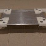
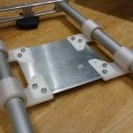
I ordered some aluminum pipes, a aluminum plate, four teflon bearings, two aluminum blocks and used a 3D printer for some other parts. After some time of sticking, milling, drilling and printing, this is the outcome.

Next, I will order a Astro devices with the linear mount.

Night Fox – Night Sky Photography Shutter Speed Calculator Android App

EDIT: Dropbox recently closed the public folder system where I store my camera database. Therefor the app was crashing while updating the database. I fixed this issue and the new version 1.3.0 is going live now.

Due to the overall great response and the high number of mails from users of my Shutter Speed Calculator i’m glad to announce here: Night Fox – Shutter Speed Calculator for Android!

The App features a simple interface to input your camera, your focal length and the tolerance in pixels. After that you can simply hit the calculate button and read the suggested speeds.

If you cannot find your camera in the list, simply write me an email or leave a comment. I can add cameras live and you just have to hit the “Download Camera File” Button to load the newest definition data. If you enjoy the app, please leave a comment and help me improve the interface and the user experience!

You can get the app for free from here:
Get it on Google Play


If you want to learn more about how it works, check out my two other posts:
https://www.tl-photography.at/stars/shutter-speed-calculator-for-night-sky-photographing/
https://www.tl-photography.at/stars/night-sky-photography-shutter-speed-calculator/

Blood Moon

Thanks to my friend Marcus, i was able to shoot some nice pictures from the moon eclipse today in the morning. Additionally it was also a Blood Super Moon! This happens pretty rarely and the next time will be 2033.

Check it out!

Super Blood Moon